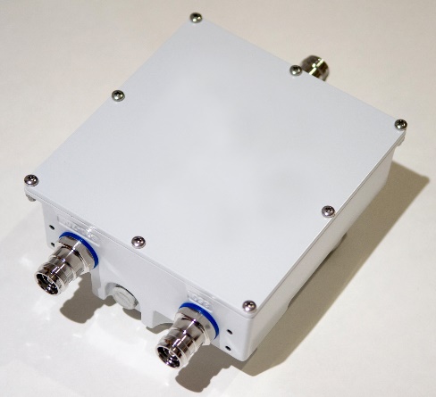
DCCM671-859-232A1
600-700 / 850 Band Diplexer
- Covers 555-787 & 824-894 MHz.
- Fully Weatherized
- Low Loss / High Isolation
- DC / ASIG Auto Sense
- Single or Dual Units Available
DCCM671-859-232A1
| Electrical Specifications | |||
| 600 – 700 MHz Band | |||
| Passband | MHz | Min | 555-787 |
| Insertion Loss | dB | Max | 0.35 |
| Return Loss | dB | Min | 22 |
| Isolation to Band 2 | dB | Min | 60 |
| Average input power | W | Max | 250 |
| Input Peak Envelope Power | W | Max | 3000 |
| 850 MHz Band | |||
| Passband | MHz | Min | 824-894 |
| Insertion Loss | dB | Max | 0.3 |
| Return Loss | dB | Min | 22 |
| Isolation to Band 1 | dB | Min | 60 |
| Average input power | W | Max | 250 |
| Input Peak Envelope Power | W | Max | 3000 |
| Intermod Products at all Ports with two +43dBm tones | dBc | Max | -156 |
| Environmental Specifications | |||
| Environmental rating | ETSI EN 300 019 class 4.1, RoHS | ||
| Ingress protection | IP67 | ||
| Temperature range | °C | -40 to +65 | |
| Temperature range | °F | -40 to +149 | |
| Wind force @ 200 km/h (125 mph) front/side | lbf | 12.9 / 7 | |
| Lightning protection all ports | RF port: ±10kA max (8/20µs), IEC 61000-4-5 | ||
| Altitude | 3,000m max | 10,000ft max | ||
| Mean Time Between Failures (MTBF) | Hrs | Min | >10^6 |
| Electronic Specifications | |||
| DC Sense and Routing Specifications | |||
| Input Voltage | DCV | 8 to 35 | |
| DC current rating | amps | Max | 1.5, current limited |
| Compatibility AISG | 1.1 / 2.0 | ||
| Combiner Function | |||
| DC on high band or low band port | DC-AISG connected to COM | ||
| DC on both ports | DC-AISG connected from high band to COM | ||
| Splitter Function | |||
| DC on COM detected | DC-AISG routed to port with AISG device | ||
| Port priority for multiple devices | 600-700 | ||
| Mechanical Specificiations | |||
| Connectors RF | 4.3-10 (F) | ||
| Ground stud | M6 x 1 (hex nut included) | ||
| Connectors Quantity | 3 | ||
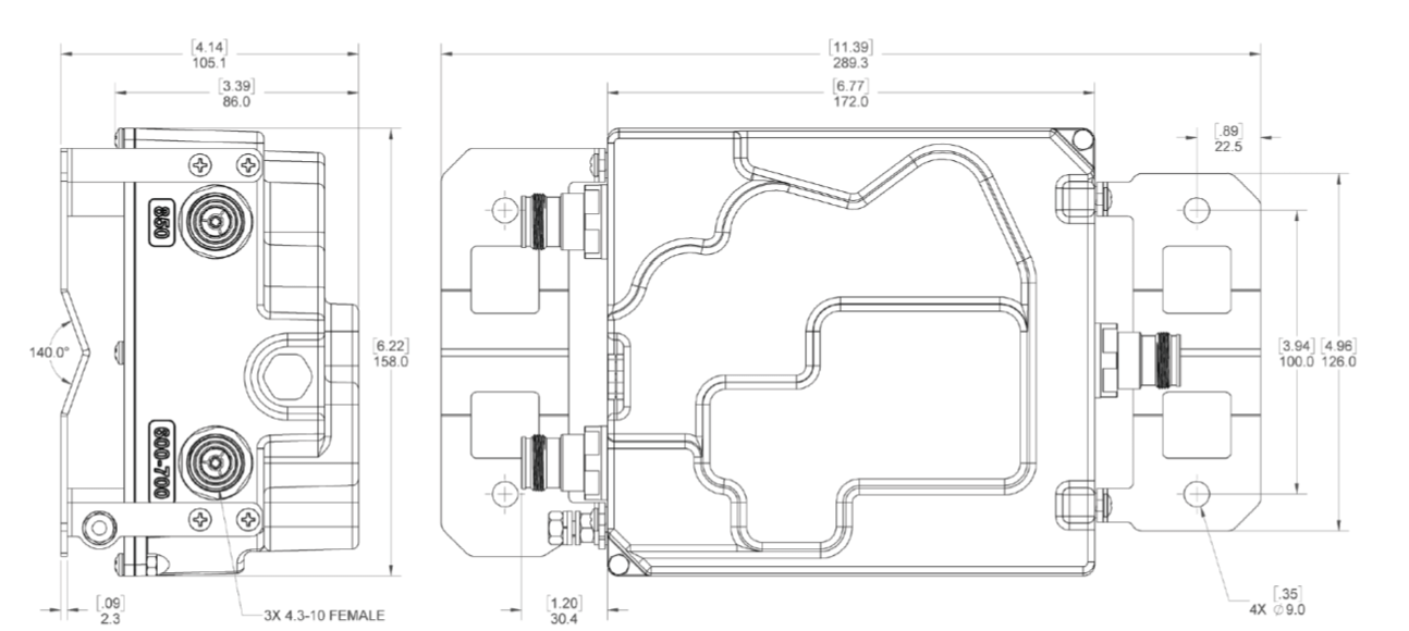
| Dimensions excluding brackets & connectors L x W x H mm (in.) | 172 x 158 x 86 (6.77 x 6.22 x 3.39) | ||
| Weight, kg (lbs.) | 2.9 (6.4) | ||
| Mounting | Pole/wall bracket supplied including two metal clamps for 45-178 mm diameter poles | ||
Outline Drawing
