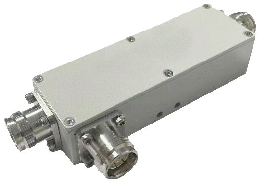
Directional Couplers
- Broadband – Covers 600 MHz to 6000 MHz
- Low Insertion Loss
- Low PIM Device, -160 dBc
- Coupling Values from 5-30 dB
- IBWave Supported
| MCV Model Number | DC5 | DC6 | DC8 | DC10 | DC13 | DC15 | DC20 | DC30 |
|---|---|---|---|---|---|---|---|---|
| Electrical | ||||||||
| Frequency Range (MHz) | 600 – 6000 MHz | |||||||
| Coupling | 5 | 6 | 8 | 10 | 13 | 15 | 20 | 30 |
| Flatness | ±1.3 | ±1.3 | ±1.4 | ±1.5 | ±1.5 | ±1.5 | ±1.5 | ±1.5 |
| Insertion Loss (dB) | ≤2.4 | ≤1.8 | ≤1.4 | ≤0.8 | ≤0.5 | ≤0.5 | ≤0.4 | ≤0.25 |
| Directivity, 600-2700 MHz (dB) | ≥20 | ≥20 | ≥20 | ≥20 | ≥20 | ≥20 | ≥20 | ≥20 |
| Directivity, 2700-3800 MHz (dB) | ≥17 | ≥17 | ≥17 | ≥17 | ≥17 | ≥17 | ≥17 | ≥17 |
| Isolation, 600-3800 MHz (dB) | ≥22 | ≥23 | ≥25 | ≥26 | ≥29 | ≥30 | ≥35 | ≥45 |
| Isolation, 3800-4800 MHz (dB) | ≥20 | ≥21 | ≥23 | ≥25 | ≥28 | ≥30 | ≥34 | ≥44 |
| Isolation, 4800-6000 MHz (dB) | ≥17 | ≥18 | ≥20 | ≥25 | ≥26 | ≥27 | ≥30 | ≥40 |
| Return Loss (dB) | ≥17 dB 600 – 2700 MHz, 16 dB 2700-6000 MHz | |||||||
| 3rd PIM (dBc) | ≤-160 @ 2×43 dBm | |||||||
| Average Power(W) | ≤300 | |||||||
| Impedance(Ω) | 50 | |||||||
| Mechanical | ||||||||
| Connector Type | See Connector Options Below | |||||||
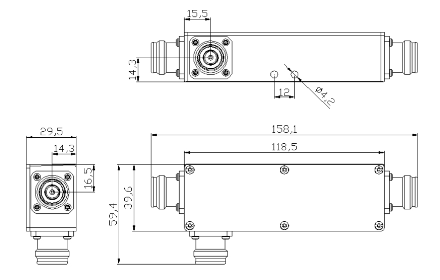
| Dimension(mm) | 118.5×39.6×29.5(4.65×1.56×1.16) | |||||||
| Weight (kg) | 0.5 | |||||||
| Environmental | ||||||||
| Ingress Protection | IP-67 (Outdoor) | |||||||
| Finish | Black Paint | |||||||
| Operating Temp (℃) | -30 ~ +65 | |||||||
| Storage Temp. (℃) | -40 ~ +75 | |||||||
| Humidity | ≤95% | |||||||
Connector Options Available
-
4.3-10.0 Female (Add -43F to Model Number)
-
7/16 DIN Female (Add -DF to Model Number)
Outline Drawing DC Series Couplers
