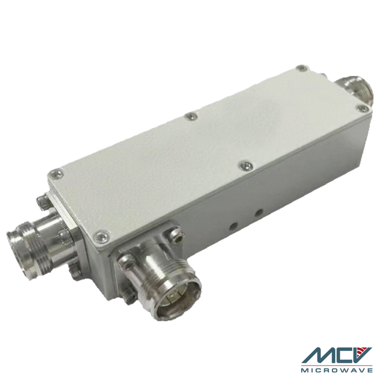
Directional Couplers
Engineered to sample RF signals with minimal disruption to the main signal path, directional couplers are essential components for signal monitoring, power measurements, and feedback control in RF systems. By coupling a defined fraction of the signal, they enable precise analysis and system diagnostics without affecting performance.
Directional Coupler by MCV
MCV directional couplers are designed for high accuracy, flat coupling, and excellent directivity across a broad frequency range. Available in multiple coupling values and connector options—including SMA, N-Type, and 2.92mm—they are ideal for use in test and measurement, telecommunications, military communications, and wireless infrastructure. Built to withstand harsh environments, MCV couplers offer consistent performance and rugged construction for both laboratory and field applications.

- Broadband – Covers 600 MHz to 6000 MHz
- Low Insertion Loss
- Low PIM Device, -160 dBc
- Coupling Values from 5-30 dB
- IBWave Supported
| MCV Model Number | DC5 | DC6 | DC8 | DC10 | DC13 | DC15 | DC20 | DC30 |
|---|---|---|---|---|---|---|---|---|
| Electrical | ||||||||
| Frequency Range (MHz) | 600 – 6000 MHz | |||||||
| Coupling | 5 | 6 | 8 | 10 | 13 | 15 | 20 | 30 |
| Flatness | ±1.3 | ±1.3 | ±1.4 | ±1.5 | ±1.5 | ±1.5 | ±1.5 | ±1.5 |
| Insertion Loss (dB) | ≤2.4 | ≤1.8 | ≤1.4 | ≤0.8 | ≤0.5 | ≤0.5 | ≤0.4 | ≤0.25 |
| Directivity, 600-2700 MHz (dB) | ≥20 | ≥20 | ≥20 | ≥20 | ≥20 | ≥20 | ≥20 | ≥20 |
| Directivity, 2700-3800 MHz (dB) | ≥17 | ≥17 | ≥17 | ≥17 | ≥17 | ≥17 | ≥17 | ≥17 |
| Isolation, 600-3800 MHz (dB) | ≥22 | ≥23 | ≥25 | ≥26 | ≥29 | ≥30 | ≥35 | ≥45 |
| Isolation, 3800-4800 MHz (dB) | ≥20 | ≥21 | ≥23 | ≥25 | ≥28 | ≥30 | ≥34 | ≥44 |
| Isolation, 4800-6000 MHz (dB) | ≥17 | ≥18 | ≥20 | ≥25 | ≥26 | ≥27 | ≥30 | ≥40 |
| Return Loss (dB) | ≥17 dB 600 – 2700 MHz, 16 dB 2700-6000 MHz | |||||||
| 3rd PIM (dBc) | ≤-160 @ 2×43 dBm | |||||||
| Average Power(W) | ≤300 | |||||||
| Impedance(Ω) | 50 | |||||||
| Mechanical | ||||||||
| Connector Type | See Connector Options Below | |||||||
| Dimension(mm) | 118.5×39.6×29.5(4.65×1.56×1.16) | |||||||
| Weight (kg) | 0.5 | |||||||
| Environmental | ||||||||
| Ingress Protection | IP-67 (Outdoor) | |||||||
| Finish | Black Paint | |||||||
| Operating Temp (℃) | -30 ~ +65 | |||||||
| Storage Temp. (℃) | -40 ~ +75 | |||||||
| Humidity | ≤95% | |||||||
Connector Options Available
-
3-10.0 Female (Add -43F to Model Number)
-
7/16 DIN Female (Add -DF to Model Number)
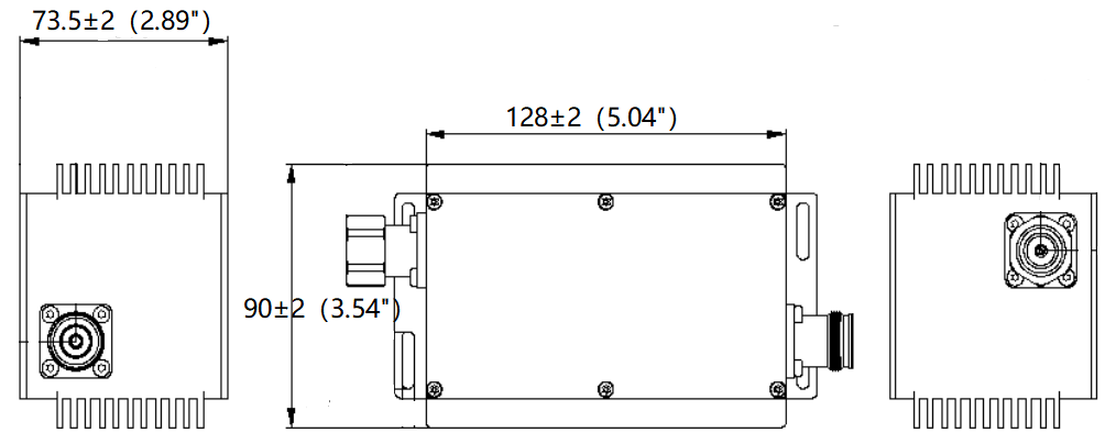
Outline Drawing DC Series Couplers

FAQ about Directional couplers
What is a directional coupler used for?
A directional coupler is used to sample a small portion of an RF signal without interrupting the main signal path. It’s commonly used for signal monitoring, power measurement, VSWR testing, and feedback control in RF systems.
What is coupling in a directional coupler?
Coupling refers to the fixed ratio of signal power that is extracted from the main transmission line and sent to the coupled port. Common coupling values include 6 dB, 10 dB, and 20 dB, depending on how much of the signal is required for measurement or analysis.
What does directivity mean in a directional coupler?
Directivity is a measure of how well the coupler isolates the forward and reverse signals. Higher directivity allows for more accurate separation of incident and reflected power, which is critical for precise measurements.
Are directional couplers bidirectional?
Most directional couplers are not bidirectional—they are designed to couple energy in only one direction (from input to output). Reversing the signal direction may result in incorrect measurements or poor performance.
In which applications are MCV directional couplers typically used?
MCV directional couplers are commonly used in test and measurement setups, telecommunications networks, radar and military systems, wireless infrastructure, and RF power monitoring applications due to their high accuracy, flat coupling, and robust construction.
How can I order directional coupler from MCV Microwave?
To place an order for directional coupler please contact us and we will help you!