This white paper addresses the growing concerns of Passive Intermodulation (PIM) and other forms of interference in 5G networks. It explores the unique challenges introduced by new frequency bands and highlights effective strategies for troubleshooting these issues. The paper reviews current industry trends in PIM detection and discusses MCV’s innovative solutions tailored for Radio Frequency Maintenance Engineers.

Introduction
The advent of 5G technology represents a major evolution in telecommunications, characterized by unprecedented data speeds, vastly reduced latency, and increased capacity, capable of supporting an immense number of connected devices simultaneously. However, the robust deployment and performance of 5G networks are significantly challenged by passive intermodulation (PIM) and various interference issues, which can severely degrade network quality.
PIM occurs when multiple signal frequencies interfere in non-linear passive components like antennas and cables, generating spurious signals that can interfere with the receiver’s ability to decode the desired signals. Furthermore, frequency allocation plays a crucial role; ensuring that signal transmissions are carefully planned to avoid frequencies that exacerbate PIM effects is vital.
Beyond PIM, 5G networks face interferences from foreign electronic devices, and the co-location and lack of synchronisation in TDD networks amplify these challenges.
The 5G Network relies on dense signal environments and higher frequency spectrums, where PIM and interference can result in increased call drops, lowered data throughput, and overall reduced network capacity.
Effective management of PIM and interference is essential for maintaining the performance integrity of 5G networks. It requires meticulous engineering to reduce PIM sources through improved component design, installation precision, and ongoing network maintenance. As such, addressing PIM and interferences effectively not only enhances the performance reliability of 5G networks but also maximizes their broad range of capabilities, making it a cornerstone for a myriad of futuristic applications ranging from IoT to ultra-reliable low-latency communications crucial for autonomous vehicles and advanced industrial automation.
5G Networks
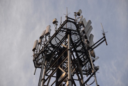
Unlike previous generations networks, 5G encompasses a wide range of radio frequencies and utilizes advanced technologies to achieve superior network efficiency and performance.
Frequency Bands and Their Usage in 5G Networks
5G networks operate across three primary frequency bands, each offering distinct benefits for different use cases:
Low-Band Spectrum (< 1 GHz): This spectrum includes frequencies such as 600 MHz, 700 MHz, and 850 MHz. Known for its extensive coverage and deep indoor penetration, low-band spectrum is crucial for providing broad, regional coverage, including in rural areas. While it ensures excellent coverage and connectivity, the low-band spectrum offers relatively lower data speeds and limited bandwidth capacity, which may not support the high-speed requirements expected in dense urban settings.
Mid-Band Spectrum (1 GHz – 6 GHz): Mid-band spectrum, which includes frequencies such as AWS, PCS, WCS, S-band 2.3GHz, 2.5 GHz, CBRS band 3.5 GHz, and C-band 3.7-4.2 GHz, strikes a balance between coverage and capacity. It offers faster speeds and lower latency compared to low-band, making it ideal for urban and suburban areas. The mid-band spectrum is extensively used for general mobile connectivity and can efficiently handle higher data demands.
High-Band Spectrum or Millimeter Wave (24 GHz and above): High-band spectrum encompasses frequencies like 28 GHz, 37 GHz, and 39 GHz. It can support extremely high data speeds and ultra-low latency, suitable for high-demand applications requiring massive real-time data transmission, such as virtual reality or live streaming in high-definition. However, due to its shorter range and higher susceptibility to physical obstructions, the high-band spectrum requires densely deployed small cells to ensure effective coverage.
Technical Specifications
- Bandwidth: The bandwidth available in 5G networks varies significantly across different spectrum bands:
- Low-Band: Offers bandwidths of approximately 10-20 MHz per channel.
- Mid-Band: Typically provides 50-100 MHz per channel.
- High-Band: Can feature bandwidths from 400 MHz up to 800 MHz or more.
- Output Power: Power levels also vary with frequency bands:
- Low-Band: Generally uses higher power levels, around 40 to 60 watts per channel, to cover larger areas.
- Mid-Band: Typically utilizes 20 to 30 watts per channel.
- High-Band: Uses lower power levels, around 1 to 3 watts per channel, due to the short-range nature of the transmissions.
- Modulation and Duplexing Techniques:
- Modulation Techniques: 5G NR (new radio) uses advanced modulation techniques like QPSK, 16QAM, 64QAM, and 256QAM to maximize spectrum efficiency.
- FDD vs. TDD:
- FDD (Frequency Division Duplexing): Predominantly used in lower frequency bands, suitable for stable, continuous communication.
- TDD (Time Division Duplexing): Commonly used in mid to high-frequency bands, offering flexibility to manage asymmetric data flows and adapt dynamically to varying traffic conditions.
5G technology has set new benchmarks in telecommunications with its high data rates, increased capacity, and significantly reduced latency. However, these network enhancements bring complex interference challenges, particularly PIM, which can severely impact the network’s efficiency and reliability. Understanding and mitigating these interferences are crucial for maintaining optimal network performance. Although 5G networks are deployed at Low, Mid and High band, this paper will focus on Interference and PIM mitigation in C-Band (3700-3980 MHz), CBRS (3550-3700 MHz), DoD (3450-3550 MHz), ESR (4000-4200MHz) AND FAA (4200-4400MHz).
The challenges
What is PIM?
Passive Intermodulation (PIM) is a critical issue in modern telecommunications, particularly with the deployment of 5G networks. PIM occurs when two or more signals mix in a non-linear manner through passive components like antennas, cables, or connectors, producing unwanted spurious signals known as passive intermodulation products.
These products are typically designated as IM2 (second-order), IM3 (third-order), IM5 (fifth-order), and so on. The third-order intermodulation product (IM3) is often the most problematic, primarily because FDD networks it is likely to fall in the receive band and can be powerful enough to interfere significantly with the receiver’s ability to decode the intended signals.
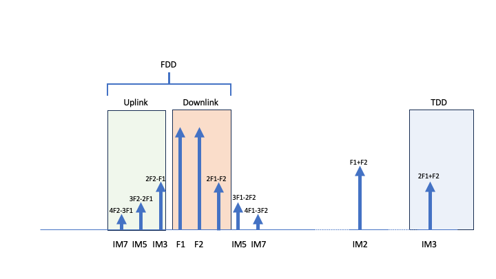
The root causes of PIM include poor metal contacts, corroded joining surfaces, or loose mechanical connections. These defects can behave like non-linear elements, mixing the signals to generate PIM. The photos below, courtesy of Kaelus—a pioneer in PIM mitigation—illustrate examples of potential PIM sources.

Loose metal parts are example of potential PIM issue

Metal swarf are example of potential PIM issue

Rusted metal and a loose screw on top of the drum, situated directly in a strong RF path, are potential sources of PIM

Rusted metal and inadequate metal-to-metal contact, such as insufficient force from the hose clamp to ensure a solid connection to the post, are examples of potential PIM issues.

Poor metal-to-metal contact: the long screw barely touches the bracket, representing another potential source of PIM.

The metal chain provides intermittent contact with the pole, a situation that can be exacerbated by high winds.
The challenge intensifies on a single mast where multiple frequencies and technologies coexist—each additional signal increases the probability of PIM occurrence. This scenario, known as cross-band PIM, becomes a significant issue as various transmit signals from different frequencies or radios mix externally, creating substantial interference within the receiver bands. These are just a couple of examples; however, there are many more possibilities. For instance, when collocating the 700 MHz Low Band (Band 12), 850 MHz (Band 5), and PCS (Band 2), the third-order intermodulation product could generate intermodulation products that fall within the CBRS band. Another example involves the collocation of the 700 MHz Low Band (Band 12) and AWS (Band 4), which could also potentially generate PIM in the CBRS band…
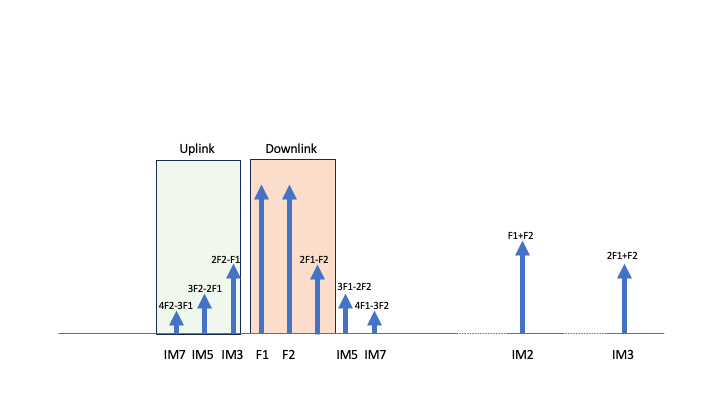
While Time Division Duplexing (TDD) was initially thought to be less susceptible to PIM due to its distinct separation of transmission and reception times, the colocation of multiple TDD and FDD systems has shown that PIM can still pose a significant problem. Signals from nearby TDD&FDD transmitters can mix, generating PIM that impacts nearby receivers. This issue underscores the complexity of managing PIM in environments dense with various signal types and emphasizes the need for meticulous planning and deployment strategies to mitigate PIM’s adverse effects on network performance.
Managing PIM effectively requires not only good design and installation practices to minimize sources of non-linearity but also ongoing monitoring and maintenance to ensure that potential PIM sources do not degrade over time. The introduction of many frequencies and the technological diversification on a single base station mast can create a “PIM nightmare,” necessitating sophisticated solutions and careful engineering to maintain optimal network performance.
Synchronisation of TDD networks
TDD synchronization can also lead to significant interference in 5G networks. The precise timing required in TDD systems, where a single frequency band is shared for both uplink and downlink communications, is critical to prevent signal overlap and subsequent interference. Misalignments in timing slots, often referred to as timing issues, can cause signal overlap, leading to substantial network inefficiency. Additionally, co-location of multiple operators or technologies can exacerbate these synchronization challenges, introducing glaring issues where misconfigurations or errors result in pronounced network disruptions. These complexities necessitate sophisticated troubleshooting and synchronization techniques to ensure optimal network performance and reliability in dense and dynamic 5G environments.
Other Interferences
Beyond PIM and synchronization challenges, 5G networks are susceptible to a variety of other interference sources. These include emissions from foreign electronic devices, interference issues at country borders where signal overlap may occur due to differing regulatory standards, and even disruptions from atmospheric conditions or topographical features that can reflect or distort signals. Each of these sources can complicate network operations, demanding sophisticated troubleshooting techniques to identify and mitigate the adverse effects efficiently and ensure robust network performance.
Effectively detecting interference in the 3.5 GHz spectrum requires filtering out adjacent bands and amplifying the signal to detect weak, yet problematic interference or PIM signals. For instance, while troubleshooting a site equipped with CBRS radios in collocation with C-Band equipment, specific filters are needed to pass the CBRS signal and attenuate the C-Band signal. This approach ensures that only relevant frequencies are analyzed, thereby improving the accuracy and efficacy of interference detection.
Industry Trends
PIM Detection Methods
Traditional PIM testing utilizes two continuous wave (CW) tones in accordance with the IEC 62037 standard, enabling RF technicians to verify the PIM levels of components as per its specifications. Although this method is effective for this purpose, it is not well-suited for cross-band and multiple tone PIM testing, which may limit its applicability in complex scenarios. An emerging alternative involves monitoring the CPRI link for any rise in the noise floor and potential PIM signatures on the uplink. However, while this method can detect the presence of interference, it provides little insight into resolving the underlying issues, thereby presenting challenges for comprehensive troubleshooting.
5G trends
The transition of 5G into various frequency bands, differences in modulation techniques (TDD vs FDD), and the hardware configuration changes (from modular to integrated systems) have all influenced how interference is managed. These trends necessitate continual adjustments in interference mitigation strategies.
MCV Solution
MCV’s tailored solution kit for RF Maintenance Engineers is designed to provide a comprehensive, portable, and versatile set of tools to be used with a spectrum monitor (not supplied by MCV) for detecting and analysing interference in 5G networks, specifically, C-Band, CBRS, DoD, ESR and FAA bands. Note: other frequency bands can be included upon request.
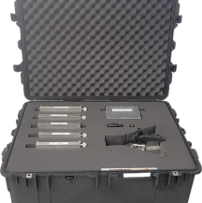
This section elaborates on each component’s specifications and the advantages they bring to interference troubleshooting in diverse field environments.
Filters

Specifications:
- Frequency Range: Each filter is tailored to specific bands, such as C-Band (3700-3980 MHz), CBRS (3550-3700 MHz), DoD (3450-3550 MHz), ESR (4000-4200MHz) and FAA (4200-4400MHz), ensuring precise coverage. More filters can be included depending on the applications.
- Insertion Loss: Kept to a maximum of 1.5 dB to minimize signal attenuation.
- Rejection: High rejection levels (>55 dB) close to the band edges to effectively isolate the desired signal band from adjacent channel interference.
- Build: Compact and robust, with weights under 3 lbs and equipped with N-type or 2.4mm connectors depending on the frequency range.
Benefits:
- Precision Filtering: The sharp cutoff characteristics ensure that only the intended frequencies are analysed, reducing the likelihood of aliasing from out-of-band signals.
- Portability: Designed for field use, these filters are both lightweight and rugged, suitable for various environmental conditions.
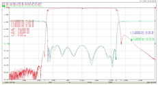
C-Ban Filter Response
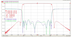
CBRS Filter Response
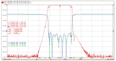
DoD Filter Response
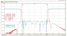
ESR Filter Response
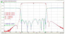
FAA Filter Response
| MCV Part number | Description |
| BCC3840-280C1 | C-Band Filter |
| BCC3625-150C1 | CBRS Filter |
| BCC3500-100C1 | DoD Filter |
| BCC4100-100C1 | ESR Filter |
| BCC4300-100C1 | FAA Filter |
LNA
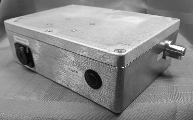
Specifications:
- Frequency Range: Covering 700 MHz to 7500 MHz to accommodate both low and mid-band frequencies.
- Gain: 30dB, providing a substantial increase in signal strength, which is crucial for detecting and amplifying weak signals that are often lost in areas with high path loss with minimum signal distortion.
- Battery Life: Capable of running for at least 6 hours on a rechargeable Li-ion battery, facilitating prolonged field operations.
- Low Noise Figure: Optimized to maintain a minimal level of added noise, enhancing the overall signal integrity and improving the quality of the received signals.
Benefits:
- Enhanced Sensitivity: The high gain level of 30dB is crucial for boosting weak signals, particularly in environments with significant path loss, ensuring that signal integrity is preserved even in challenging conditions.
- Operational Flexibility: Battery-powered and portable, these LNAs support mobile testing without the need for a continuous power supply, allowing for greater versatility and ease of use in field operations.
- Improved Signal Quality: A low noise figure ensures that the signal-to-noise ratio is optimized, resulting in clearer and more accurate signal detection and analysis.
| MCV Part number | Description |
| BCC5-ALB-A1-L | LNA Module |
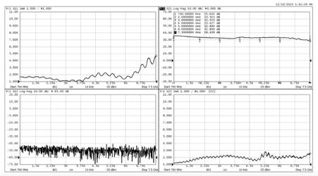
LNA Response
ANTENNA
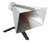
Specifications:
- Frequency Range: 1000-7500 MHz, making them suitable for mid to high-band 5G frequencies.
- Gain: At least 10 dB to ensure adequate signal strength is captured.
- Front-to-Back Ratio: Minimum of 20 dB, enhancing directional sensitivity and minimizing interference from the back side.
Benefits:
- Directional Accuracy: High F/B ratio helps in precisely locating the source of interference, which is critical in densely populated network environments.
- Wide Coverage: Supports a broad spectrum, facilitating comprehensive field testing across multiple 5G bands.
- Fitted with an ergonomic handle, the antenna can be easily manoeuvred and positioned with minimal effort to detect the direction of interference.
| MCV Part number | Description |
| BCC5-ALB-A1-A | Antenna |
5G RFME Test Kit

Specifications:
- Kit Packaging: Each kit is packed in a Pelican case or equivalent, known for their durability and security, with customization to hold all individual components securely.
- Compatibility: Designed to be agnostic of test equipment, the components can interface with various spectrum analyzers or monitoring systems, ensuring wide applicability
Benefits:
- Comprehensive Solution: By combining filters, LNAs, and antennas in a single kit, RF Maintenance Engineers are equipped with all necessary tools to detect, analyze, and mitigate interference effectively.
- Ease of Use: The agnostic nature of the kit components allows seamless integration with existing testing apparatus, making the kit a versatile addition to any RFME’s toolkit.
| MCV Part number | Description |
| BCC5-ALB-A1 | 5G RFME Test Kit |
Using the MCV Kit for Interference Detection
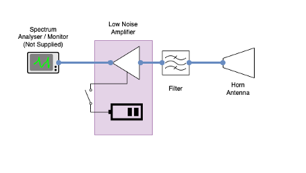
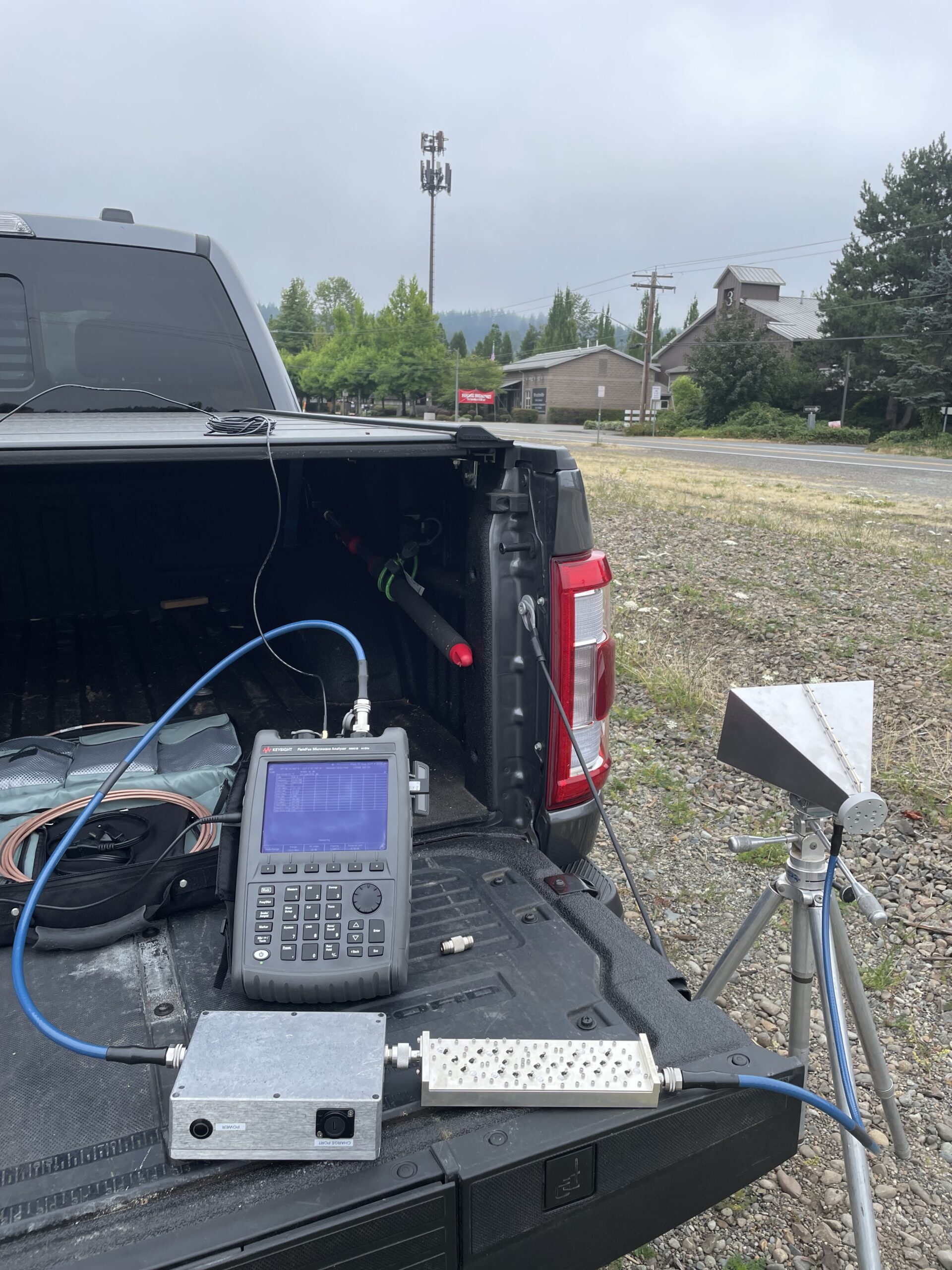
The MCV kit, designed for interference detection, includes a directional horn antenna, a filter, and a Low Noise Amplifier (LNA), all of which are to be connected to a spectrum analyzer (not supplied by MCV).
To effectively utilize the kit, follow these steps:
-
- Setup: Start by connecting the directional horn antenna to the filter, then link the filter to the LNA. Connect the LNA’s output to your spectrum analyzer. This setup is crucial for accurately capturing and analyzing signals. The filter is essential as it helps protect the LNA and spectrum analyzer from strong nearby signals.
- Monitoring: Power on the spectrum analyzer and begin monitoring the signal strength. Use the initial readings as a baseline to detect any anomalies in the signal.
- Antenna Positioning: Carefully adjust the position of the directional horn antenna to locate the point of maximum signal strength. The directional nature of the horn antenna allows for precise adjustments and more accurate localization of signal sources. Monitor the changes in signal strength as you adjust the antenna’s position.
- Signal Triangulation: After identifying the peak signal strength, note the antenna’s position. Employ a triangulation method by relocating the antenna to different locations while maintaining the orientation that yielded the highest signal strength. This technique is crucial for accurately pinpointing the geographic source of the interference.
- Interference Source Identification: Through repeated triangulation, determine the exact location of the interference, enabling targeted troubleshooting and resolution.
- Mitigate the Interference: Once the position and nature of the interferer are clearly understood, take appropriate actions to mitigate the issue. This may involve removing the source of interference, often referred to as PIM hygiene (e.g., replacing faulty components or adjusting problematic setups), or repositioning the TDD antenna to minimize the glaring effects. This step ensures that the interference impact on network performance is significantly reduced or eliminated.
By adhering to these steps with the MCV kit, RF technicians can effectively locate and address sources of interference, ensuring optimal network performance and reliability.
Conclusion
The advancement of 5G networks, while beneficial, introduces significant interference challenges that can undermine network performance. The MCV solution kit not only addresses the specific needs of interference troubleshooting in 5G networks but also offers the flexibility, precision, and ease of use required for effective field operations. By integrating high-quality components into a portable and robust package, MCV ensures that RF engineers are well-equipped to handle the complexities of modern RF environments. This solution stands out by providing an adaptable platform compatible with a wide range of testing equipment, making it an invaluable asset for maintaining 5G network integrity.
Explore Advanced Solutions
Interested in learning more about effectively managing PIM and other interferences in 5G networks?
Our team of experts is ready to assist you with innovative solutions tailored to your specific needs. Reach out for more information and discover how we can enhance your network’s performance and reliability.
About MCV Microwave
MCV Microwave East, Inc. is an RF component and integrated assembly company focused on designing, manufacturing and delivering key filter products for mission-critical and semiconductor industries. We have over a century of combined experience as trusted partners in military, aerospace, industrial and commercial markets. For more information, visit www.mcv-microwave.com.
